![]()
One of EXITECH's software tools is HYDREX™, a graphical hydraulic flow network model builder that allows rapid development and checkout of real-time simulation models suitable for nuclear power plant full-scope training simulators.
HYDREX™ includes a graphical user interface tool and a library of model components that allow the user to design and develop a system model in four steps. These four steps are as follows.
Step 1: Component Selection
HYDREX™ utilizes the DataViews™ graphical editor to simplify the design of system models. This allows the user to select and arrange model components with simple point/click/drag mouse operations.
The current model component library includes the basic components found in a typical hydraulic network model, including:
- internal nodes
- external pressure nodes or boundary conditions
- pumps
- tanks
- valves
- heat exchangers
- filter/demineralizers
- flow orifices
Additional components will be added as necessary.
Step 2: Component Linkage
Compontents are linked together using flow links. Flow links are specified with simple point/click/drag mouse operations and are used to connect internal and external pressure nodes and model equipment components such as pumps, tanks, heat exchangers, and filter/demineralizers.
Step 3: Component Configuration.png)
After the model components are arranged and connected with the flow links the physical characteristics, system variable interfaces and initialization data of each component may be specified. A double-click on a compnent will access a pop-up window that displays all pertinent information. Figure 1 shows the pop-up window for an internal pressure node.
Physical properties of model components, such as nodal elevations, tank characteristics, or pump characteristics are entered using model component pop-up windows.
Initialization data is also specified using component pop-up windows. This data is used to compute model constants such as flow admittances, pump head constants, or heat transfer constants and is also used for model variable initiation.
HYDREX™ is linked to the simulator database and initial Condition files to simplify specification of system interfaces and initialization data.
As a visual cue for the user, HYDREX™ changes component colors from red to black when all required component information is complete. When all components are displayed in black, Step 3 is complete and the system model is ready to be generated.
Step 4: Model Generation
This step is the easiest part of the process of creating a system model for the user. All of the information from Steps 1 - 3 is contained in a relational database. A single mouse click will take this information and create all source code and data files that are needed to checkout and deploy the model.
HYDREX Output
HYDREX™ output includes documented Fortran model source code, a stand-alone HTML version of the model, and data files that simplify installation of the model on the simulator. Data files are designed to be used by Chattanooga™ utilities such as DBAdd, Radar, Conlnit and ICMod.
Fortran Source Code" Fortran versions of the model subroutine and matrix subroutine are generated that are ready to compile and link into a simulator task. "Database ADD File" A database ADD file is generated that can be used to add model variables and constants to the simulator database. Chattanooga's DBAdd program will accept this batch file as input to allow addition of model constants and variables with a single mouse-click. "Constant INIT File" A constant INIT file is generated containing values for each model constant. This file may be loaded using Radar, Chattanooga's Real Time Variable Monitor, and can also be automatically loaded each time the simulator is reset. "Initial Condition INIT File" A variable INIT file is generated containing values for each model variable. Like the constant INIT file, this file may be loaded using Radar, Chattanooga's Real Time Variable Monitor, or can be automatically loaded each time the simulator is reset. Chattanooga's IC Editor can process this file to initialize the model without having to resnap all IC's.
Model Considerations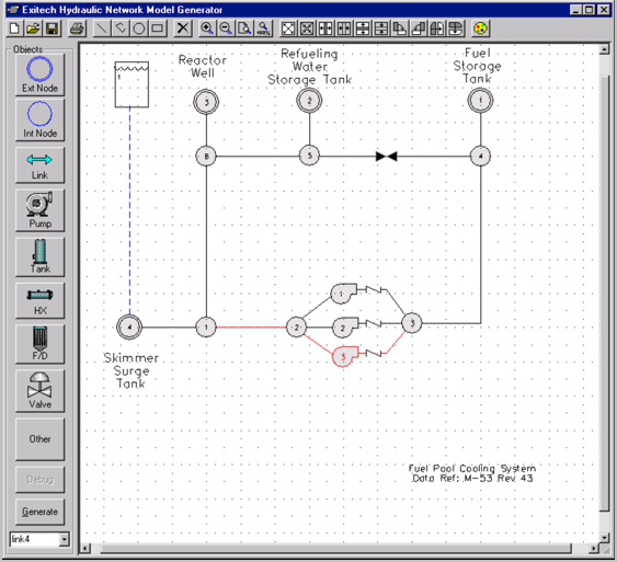.png)
HYDREX™ creates source code and data files from pre-defined templates. At the present time, the hydraulic flow network model templates are complete. Additional templates for HVAC flow networks and Electrical Distribution networks are planned for the near future. Enhancements to the model builder output can be made by simply editing or creating new Model Templates.
The hydraulic flow network model includes the following:
- Elevation of each internal and external (boundary) node
- Liquid/vapor mixture based on nodal thermodynamic conditions
- Flashing of liquid/vapor for external flow based on boundary conditions
- Pump cavitation effects
- Nodal liquid temperature calculations
- Nodal activity/conductivity mixing calculations
- Radioactive decay of dissolved species
- Consideration of low suction levels
- Ambient heat transfer
- Pipe wall temperature calculations using heat slabs
- Leak malfunctions at any pressure node
HYDREX™ models are capable of simulating conditions found in Balance-of-Plant systems such as Condensate and Feedwater, Emergency Core Cooling, Cooling Water/Circ Water, Reactor Water Cleanup, and virtually any hydraulic system besides the BWR Reactor Recirculation system and PWR Primary/Secondary Coolant systems.
By combining a user-friendly interface with detailed model templates. HYDREX™ simplifies the process of generating and integrating complete hydraulic system models.